
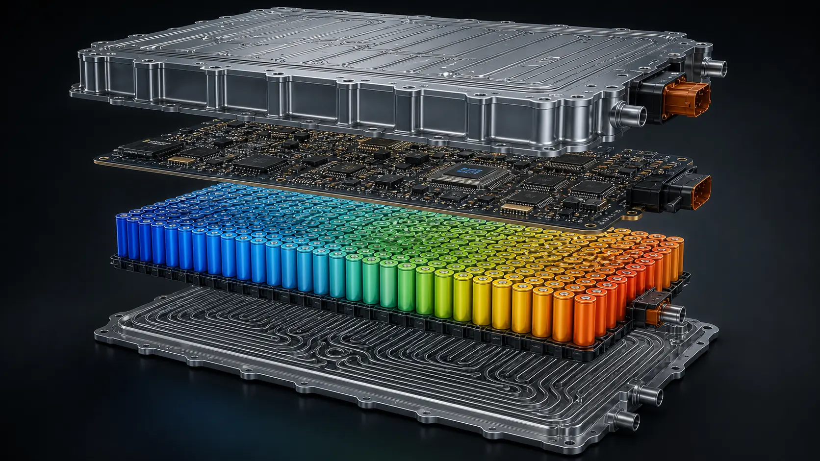
The thermal problem in lithium-ion battery pack design is not new. But it is getting harder to solve using the workflow most engineering teams are still relying on.
As cell energy density climbs — NMC cells are pushing past 250 Wh/kg today, with research targets exceeding 400 Wh/kg by 2030 — the thermal load inside an increasingly compact pack is reaching levels that break traditional design-test-fix methodologies. Most Li-ion chemistries operate within a safe electrochemical window of 15°C to 35°C. Sustained operation above 60°C triggers accelerated capacity fade. Cross 80–100°C, depending on cell chemistry and format, and the risk of thermal runaway rises sharply — a self-sustaining exothermic cascade that can spike cell temperatures above 800°C in under 30 seconds.
The data on this is not ambiguous. Industry analysis indicates that approximately 28–32% of battery pack designs entering physical DVT require significant thermal architecture changes. That is not primarily a materials failure or a chemistry failure. It is a simulation gap — a failure to front-load validation to where it is cheapest and fastest to run it.
The Problem With Test-First Workflows
Most BMS thermal validation still follows a familiar and expensive sequence: build physical prototype, run thermal chamber testing, analyze failure modes, revise design, repeat. Each physical prototype iteration in an Indian EV program — accounting for cell procurement, pack assembly, enclosure fabrication, and testing — costs between ₹35 lakhs and ₹80 lakhs depending on pack configuration and test scope. Three redesign iterations before a validated thermal baseline is established means ₹1–2.4 crore spent confirming what simulation could have predicted before the first part was ordered.
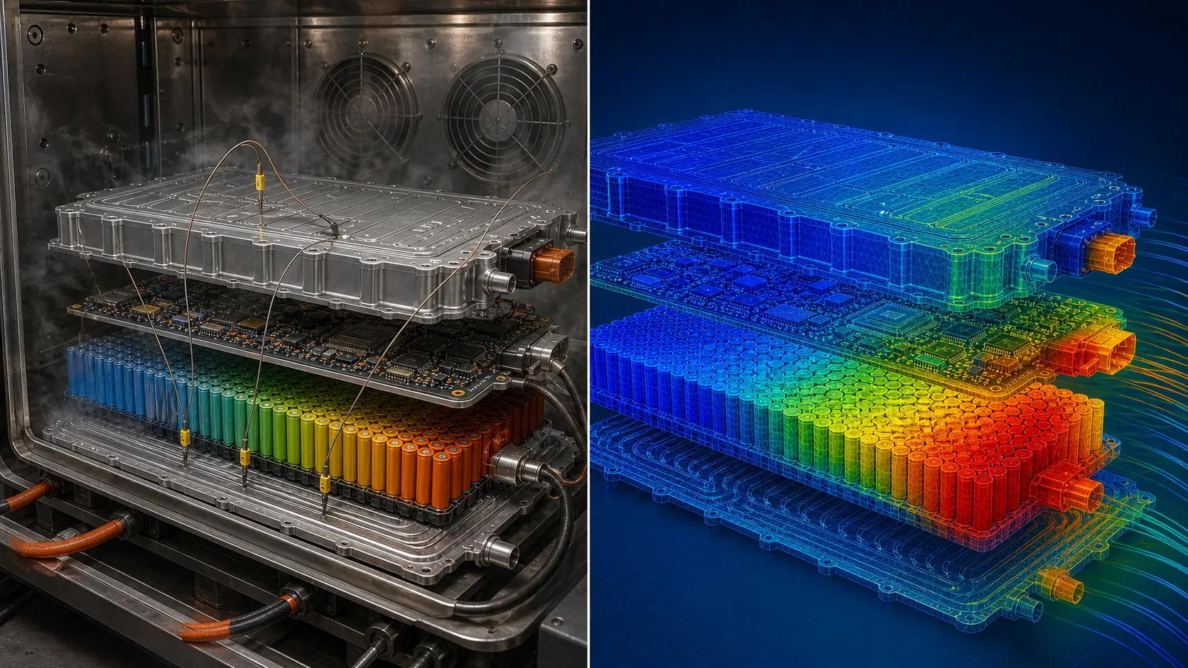
Beyond direct cost, there is the schedule impact. A single thermal test-and-redesign cycle takes 8 to 14 weeks end-to-end. For a 24-month product development program, that compression does not get absorbed without consequences — and those consequences arrive in DVT as incomplete validation, deferred safety testing, and design compromises made under deadline pressure.
Where Simulation Changes the Equation
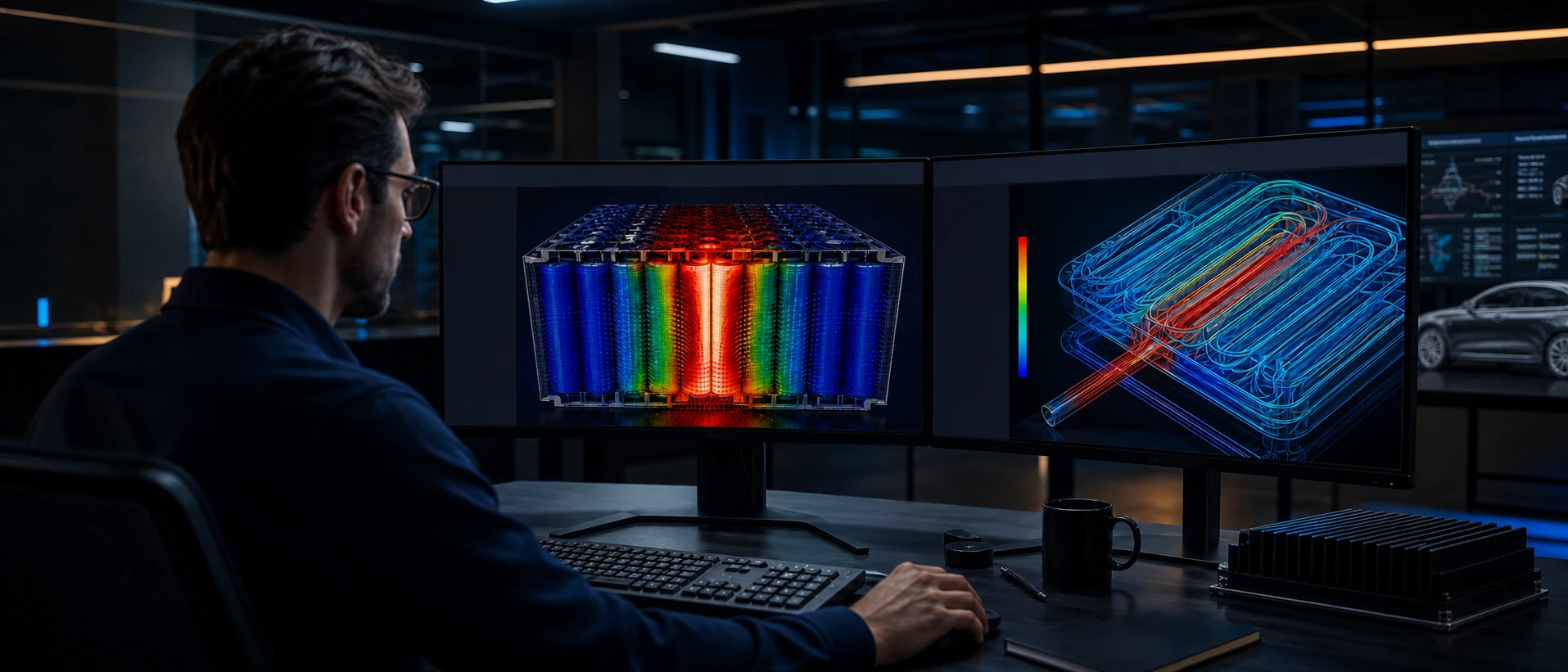
Multi-physics simulation — combining computational fluid dynamics (CFD) for conjugate heat transfer analysis with electrochemical-thermal battery modeling — can reproduce pack-level thermal behavior under charge, discharge, and abuse conditions with sufficient accuracy to drive real design decisions before a single prototype is built.
Three simulation workflows deliver the highest return at EVT stage or earlier:
Cooling architecture optimization
CFD analysis of cooling plate channel geometry, coolant flow rates, and thermal interface material (TIM) placement allows parametric sweeps across design variants in days. The target output is the minimum coolant flow rate required to maintain maximum cell surface temperature below your design limit under peak discharge — typically 3C to 5C for commercial EV applications.
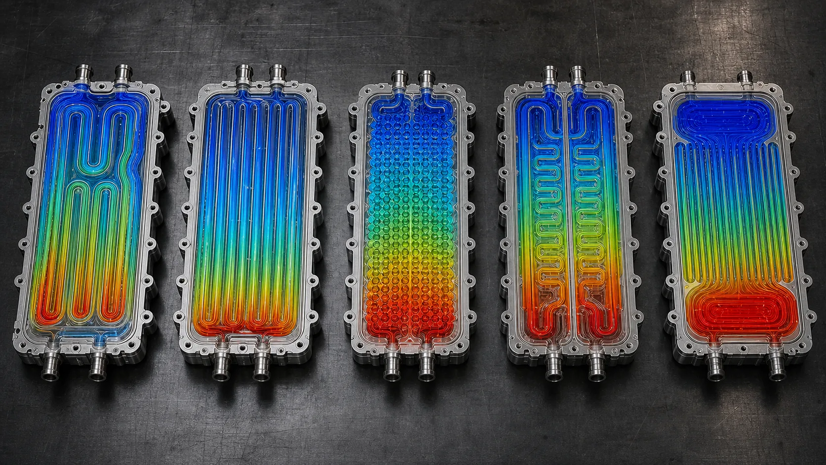
Cell-to-cell temperature uniformity mapping
A temperature differential of more than 5°C across adjacent cells in a module is a documented contributor to non-uniform State of Health degradation and capacity fade over the product lifetime. Simulation maps this distribution under standard drive cycle conditions before module assembly — so corrections happen in CAD, not in the test chamber.
Electrochemical-thermal abuse condition modeling
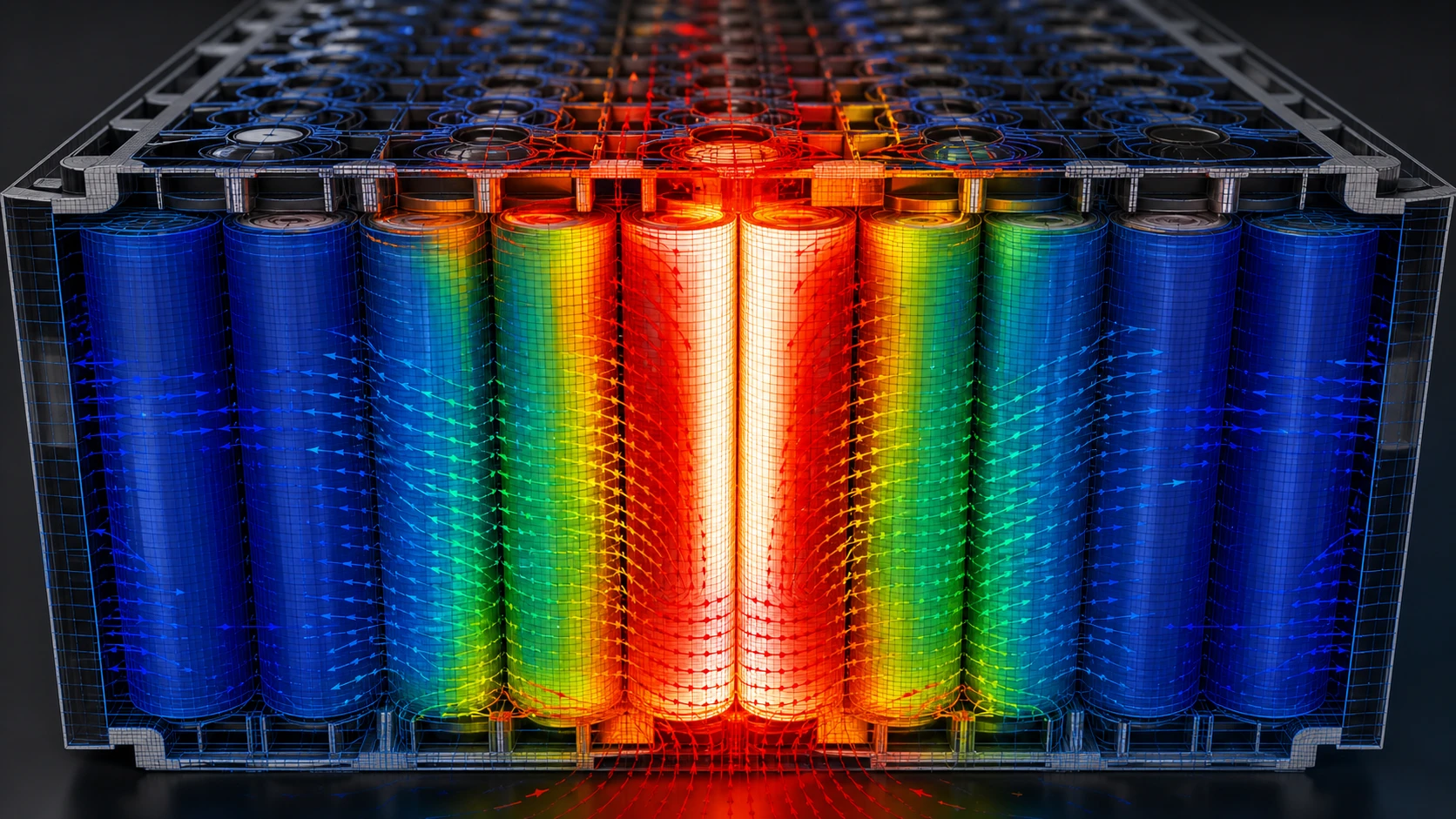
Nail penetration, external short circuit, and overcharge scenarios are dangerous and expensive to run at scale in physical testing. Coupled electrochemical-thermal simulation models thermal runaway propagation paths before a single physical abuse test is required, enabling decisions about cell isolation geometry and thermal barrier design to be finalized earlier.
The Numbers That Should Drive Your Decision
The global BMS market was valued at approximately $8.5 billion in 2023 and is projected to reach $33 billion by 2030, growing at a CAGR of roughly 21%. India's EV adoption is moving faster — 49% year-on-year growth in EV registrations, with a government target of 30% EV penetration in total vehicle sales by 2030.
In that competitive environment, engineering teams that front-load simulation report a 50–60% reduction in physical prototype iterations compared to test-first workflows. That is a structural efficiency gain. It directly translates to faster DVT entry, fewer design-freeze surprises, and a higher probability of hitting launch windows without compromise.
What Your Team Should Be Running Before the First Build
If you are in early EVT or pre-EVT on an active BMS program and these three simulations are not on your project plan, they need to be:
- Conjugate heat transfer analysis of your cooling architecture at peak discharge rate. Validate maximum cell surface temperature against your design limit.
- Module-level temperature uniformity study under standard drive cycle. Confirm that ΔT across all cells stays below 5°C.
- Electrochemical-thermal model of your worst-case ambient scenario. For most Indian applications, that means 45°C ambient at full discharge.
Physical testing will always be required. The question is what it validates — a design that was already optimized in simulation, or one still carrying unresolved thermal risk when the first prototype is assembled.
Is Your Battery Pack Thermal Architecture Simulation-Ready?
Kaizenat's CAE engineers offer a free consultation on battery pack thermal simulation — cooling architecture, temperature uniformity, and abuse condition modeling. Specific, actionable feedback before your next prototype cycle.